How to build your own stereo vision with FLIR machine vision cameras.
Applicable Products
All FLIR machine vision cameras
Application Note Description
The purpose of this Technical Application Note is to provide an example of how you can build your own stereo vision system using two FLIR machine vision ice-cube sized cased cameras with the processing executed by a PC using OpenCV algorithms and the Spinnaker API.
Note: For another approach with a smaller physical footprint, see How to Build a Custom Embedded Stereo System for Depth Perception, using two board level cameras and the Quartet Embedded Solution for TX2.
Overview
Stereo Vision is an imaging technique that can provide full field of view 3D measurements in an unstructured and dynamic environment. Each pixel in a digital camera image collects light that reaches the camera along a 3D ray. If a feature in the world can be identified as a pixel location in an image, we know that this feature lies on the 3D ray associated with that pixel. If we use multiple cameras, we can obtain multiple rays. The intersection of these rays is the 3D location of the feature.
In this example, two cameras are fixed in place and images of a known calibration target are taken. From these images, lens distortion is removed and the images are rectified. For dense stereo algorithms, typically the images from the cameras must be remapped to an image that fits a pin-hole camera model. This remapped image is called the rectified image. An algorithm then finds matches of pixels or features in the image to determine disparity.
Disparity is the distance in pixels that a feature or block of pixels is found from in the left rectified image to the right. A larger disparity means that a feature or object is nearer to the cameras (imaging plane) and a smaller disparity means the object is further away from the cameras. Stereo vision uses disparity to calculate the distance away from an object.
PC Configuration
- Windows 7 64x
- ASUS Z97-PRO motherboard
- Intel Core i7-4790 CPU @ 3.60Hz
- 8 GB RAM
Hardware Setup
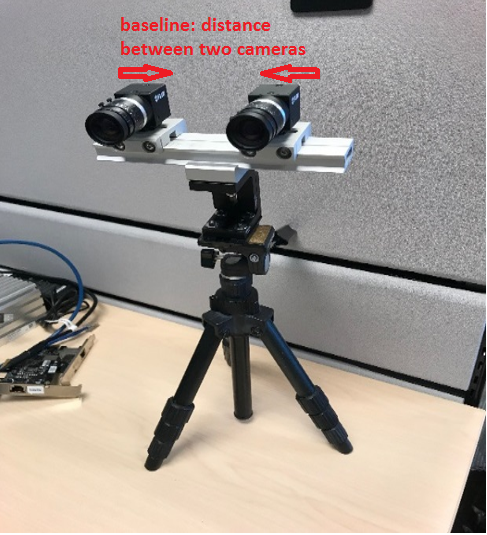
In this application note, two cameras were mounted on THORLABS brackets, dovetail rails and a SLIK tripod to make sure they are leveled. The cameras need to be firmly fixed in place relative to each other. Small changes, especially in the vertical axis, will misalign the scan lines used by the algorithm to find matches. This misalignment can cause a poor disparity map.
Cameras:
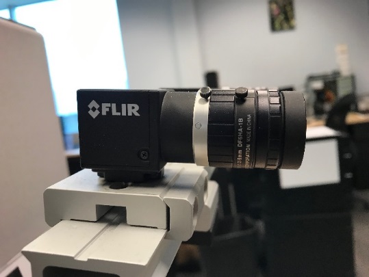
- 2 x BFS-U3-50S5C-C (firmware version 1803.0.167.0)
Lenses:
- Fujinon DF6HA-1B 6 mm Lenses
Mounting Equipment:
- THORLABS: https://www.thorlabs.com
- AB90 with AB90A/M mounted on a ACC-01-0011 Tripod Adapter
- Combination equivalent to the mounting clamps used:
- XT34C2 – 3 x
- XT34D2-30 – 3 x
- XT34DP-500 Rail (Cut down to 200 mm)
- Cameras mounted to XT34D2-30 using ACC-01-0003 adapter
- SLIK 450G Tripod
- Baseline used: 7.88 cm (distance between centers of camera sensors)
Software Requirements
Visual Studio 2015
Spinnaker SDK 1.21.0.61 or later
OpenCV 3.4 (3.4.3 minimum) https://opencv.org/releases.html
1. Download Win pack then install OpenCV into “C:\OpenCV\build\x64\vc15”
2. Environment Variables
- Add/Set “OPENCV_DIR” as “C:\OpenCV\build\x64\vc15”
- Add “%OPENCV_DIR%\bin” to Path
3. Configure OpenCV in Visual Studio
- Follow steps under “Configure OpenCV in Visual Studio” section in Getting Started with OpenCV
Calibration Pattern
In this technical application note, a checkerboard pattern was printed out for stereo calibration. OpenCV interpolates the location of each corner to the sub-pixel level. Then it uses those positions to calculate matrices for intrinsic distortion, extrinsic rotation and translation of cameras relative to each other. Ideally, this pattern should be held in place. To maximize the field of view coverage for calibration, move the pattern close or use a larger pattern.
Checkerboard pattern download: https://markhedleyjones.com/projects/calibration-checkerboard-collection.
Square size of checkerboard pattern used: 3.0 cm x 3.0 cm.

Lens Adjustment
For stereo vision to work, images need to have enough detail to find corresponding pixels in the rectified images. The lens should be in focus for most of the range of distances your application requires. Closing the aperture can increase the depth of field so that a greater range of distances is in focus but this will decrease the amount of light reaching the sensor.
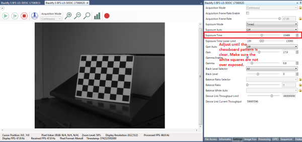
For best results while calibrating, in SpinView set Exposure Auto to Off and change it so the checkerboard pattern is clear and the white squares are not over exposed. After the calibration files are generated by the C++ console application, gain and exposure can be set to auto in SpinView.
Tighten the adjustment knobs on the lens to keep the focus and aperture fixed after configuring the preferred exposure setting.
How to Display Real-time Disparity Map
1. Download opencv_stereo_vision.zip.
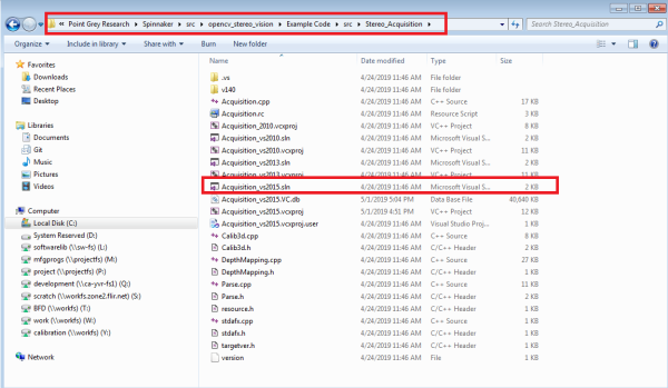
The opencv_stereo_vision folder should be placed in the same folder location as the other Spinnaker examples. This is the src folder for the Spinnaker SDK (the default location for the source folder is C:\Program Files\Point Grey Research\Spinnaker\src).
2. Ensure you can successfully build the Stereo_Acquisition_vs2015.sln file which is located under opencv_stereo_vision\Example Code\src\Stereo_Acquisition.
3. Run the Stereo_Acquisition_v140.exe provided in opencv_stereo_vision.zip file.
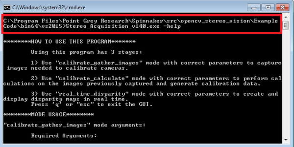
4. After you have successfully built Stereo_Acquisition_vs2015.sln, open command prompt and navigate to opencv_stereo_vision\Example Code\bin64\vs2015 folder.
5. Enter command: Stereo_Acquisition_v140.exe –help to see instructions on how to run this program.
関連記事の配信登録をする
Calibrate Gather Images Mode
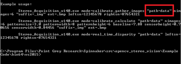
This mode is to capture images needed to calibrate cameras. In this program, each camera is software-triggered to capture 6 images (12 images in total) upon user input. These images are used later for calibration. You can set the path for where the images will be stored using the command below:
In order for the OpenCV algorithm to find matches of pixels or features in these images, it is important to capture an image of the target at different positions within the ROI (Region of Interest).
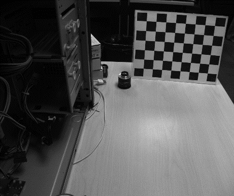
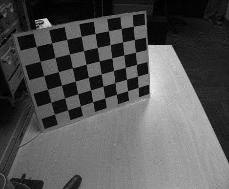
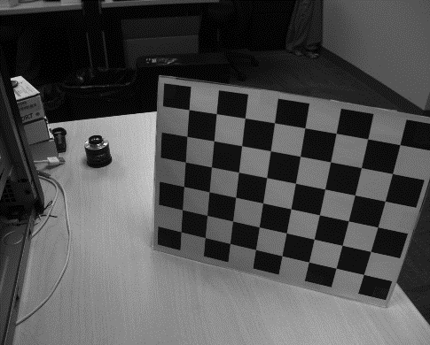
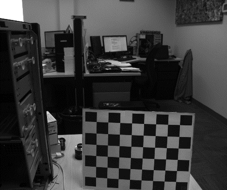
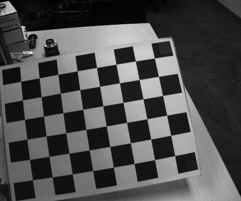
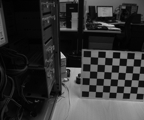
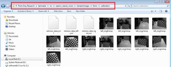
Note: these are examples of 6 uncropped, unprocessed images taken straight from one of the two cameras while running calibrate_gather_images, to be used by the opencv algorithm in calibrate_calculate
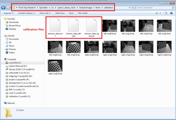
Calibrate Calculate Mode
This mode is to perform calculations on the images previously captured and generate calibration data. When the “calibrate_calculate” mode is executed, three .yml (calibration) files are generated - 2 intrinsic files and 1 extrinsic file. The path for these calibration files must be the same as where the calibration images are saved. The extrinsic file (about 3 KB) contains the required matrices and physical parameters for both cameras to use stereo vision in OpenCV.
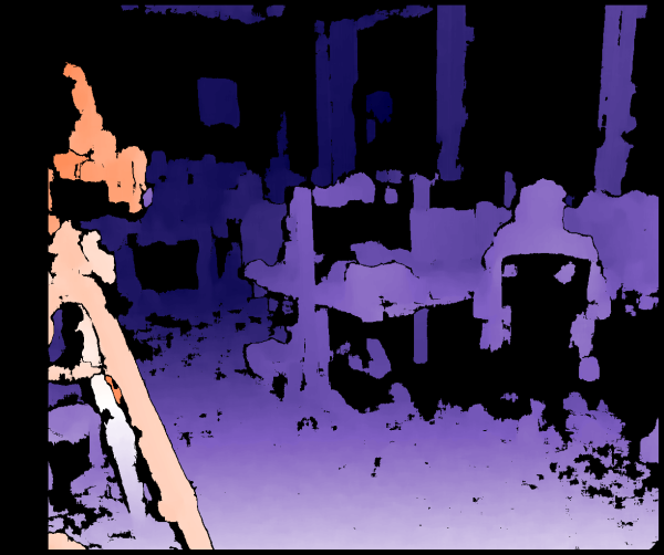
Real Time Disparity Mode
This mode is to create and display disparity maps in real time.
The DepthMapping() function in DepthMapping.cpp is called (found in C:\Program Files\Point Grey Research\Spinnaker\src\opencv_stereo_vision\Example Code\src\Stereo_Acquisition) to load the extrinsic file created from calibrate_calculate and display the disparity maps as shown below:
Physical Properties for Calibration
Some physical properties are needed aside from the images captured for calculating depth from disparity. The data set used in Stereo_Acquisition_vs2015.sln are:
- Patternsize (size of checkerboard squares): 3 cm
- Patternwidth (number of inner square edges of checkerboard lengthwise): 8
- Patternheight (number of inner square edges of checkerboard heightwise): 6
- Baseline (distance between centers of camera sensors): 7.88 cm
- Sensor width and height. These can be found using the sensor resolution and pixel size. For example, BFS-U3-50S5C-C has resolution of 2448 x 2048 and pixel size of 3.45 um. Sensor width = 0.00000345 * 2448 = 0.0084456 m = 0.84456 cm
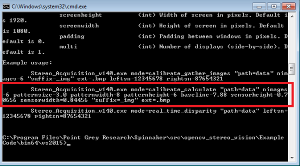
When you set up your own stereo vision system, you need to change the values for these properties according to your camera setup. For example, the baseline used in this example is 7.88 cm. However, if your application requires a different baseline, you can change this value when executing Stereo_Acquisition_v140.exe mode = calibrate_calculate as shown above.
Note: Example uses centimeters for all physical lengths.
Displaying Disparity Images
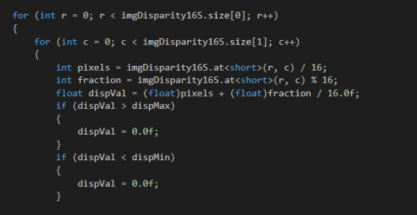
The OpenCV StereoBM and StereoSGBM algorithms found in the DepthMapping.cpp file are used to provide disparity in 16 bits. The last 4 bits are fractional so the disparity is accurate to 1/16 pixels. To get the actual float value, you need to separate the output (short int) into its fractional and whole components, cast as float, and finally add them.
Resolution Performance
High resolutions do not work as well with the Stereo Block Matching algorithm as they significantly increase the time to process and make real time disparity calculations impractical. High resolutions also require more accurate calibration. Being ¼ of a pixel off with 1000 x 700 is not too substantial. However, that inaccuracy in calibration makes a bigger difference at 2400 x 2000 where it would be nearly a pixel off.
In theory, a higher resolution can give higher accuracy disparity maps, however in practice it is hard to achieve. Binning can be used to get a smaller resolution without modifying sensor size calculations.
Calibration Sequence
Calibration sequence done with Stereo_Acquisition_vs2015.sln:
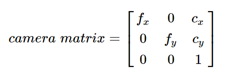
1. Intrinsic calibration is done first which involves each camera individually. It is also called camera matrix. Intrinsic parameters are specific to a camera and they include information such as focal length and optical centers.
Use findCheckerboardCorners() and cornerSubPix() found in Calib3d.cpp for intrinsic calibration.
2. Then stereoCalibration() is done which uses the intrinsic calibration and provides relative extrinsic information.
Optimizations
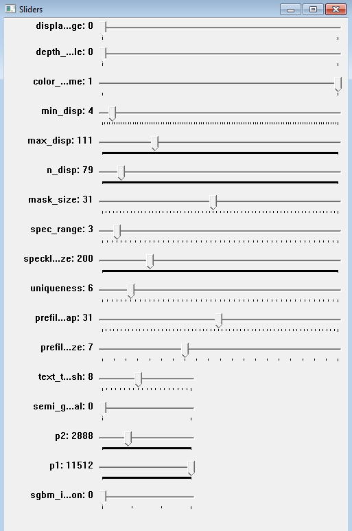
By default, the calibration settings are hard coded in Acquisition_vs2015.sln (C:\Program Files\Point Grey Research\Spinnaker\src\opencv_stereo_vision\Example Code\src\Stereo_Acquisition) to work well for around 1000 x 800 resolution. Stereo mask size and ndisparities in disparity map are the biggest factors. You can change these settings when you execute Stereo_Acquisition_v140.exe in “real_time_disparity” mode using sliders.
Changing the stereo mask size changes the size of the pixel block that is matched between the images and ndisparities is the range of disparity values. A large range of disparities is needed for closer objects.
Results
2 x BFS-U3-50S5C
2 x 6 mm Lens (Fujinon DF6HA-1B)
- Baseline of 7.88 cm
- Square size of checkerboard pattern was 3.0 cm
- Calculated Sensor Width and Height: 0.84456 cm x 0.70656 cm
This setup can detect changes accurate to around 2 millimeters at 1.2 meters away.
Note: The default values provided in the example assume you are using the exact setup documented here.